A couple of nice electrical discharge machining images I found:
Image from web page 177 of “The inventions : researches and writing of Nikola Tesla, with unique reference to his work in polyphase currents and high potential lighting” (1894)

Image by World wide web Archive Book Pictures
Identifier: inventionsresear00martuoft
Title: The inventions : researches and writing of Nikola Tesla, with special reference to his perform in polyphase currents and higher possible lighting
Year: 1894 (1890s)
Authors: Martin, Thomas Commerford, 1856-1924 Tesla, Nikola, 1856-1943
Subjects: Electric currents, Alternating Electric engineering
Publisher: New York : The Electrical Engineer
Contributing Library: Gerstein – University of Toronto
Digitizing Sponsor: University of Toronto
View Book Page: Book Viewer
About This Book: Catalog Entry
View All Photos: All Photos From Book
Click right here to view book on the web to see this illustration in context in a browseable on-line version of this book.
Text Appearing Prior to Image:
iucli as an inch of wax, hard nd> 158 INVENTIONS OF NIKOLA TESLA. Iter, gla,«^s, or any »»tlKr insulating suhstanc-e. This limits greatlythe output of the coil, hut I will later show how I have been ableto overcome to a considerahk- extent this disadvantage in theordinary coil. In addition to the prospective, the intensity of the stivams dej>ends onthe frequency but if the coil be really large they show them-selves, no matter how l(»w the fre»iuencies used. For instance,in a extremely massive coil of a resistance of (»7,(l(t ohms, constructedbv me some time ago, they seem with as l(»was 10(1 alternationsper second and less, the hisulation of tlie secondary being | inchof ebonite. When really intense they i)ni(luce a noise shnilar t(»that ])roduced by the charging of a Iloltz machine, but iiiuclimore ])owerful, and they emit a sturdy smell of ozone. Thelower the freipiency, the much more apt tliey arc t(» suddenly injuretli«- coil. AVith excessively liigh fre(|Uenciis tln-y may jiass freely
Text Appearing Right after Image:
Ft(. 101. wirlioiit |ii-ti(hicing any utiicr cflicT than to heat the insulationslowly and unifoi-ndy. The existence oi these streams shows the im])ortance of con-structing an high-priced coil so as to |>(rmit of ones seeingthrough the tube surrounding tlie major, and tlu- latter shouldbe effortlessly exchangeable or else the space in between the |)rimaryand secondary must be fully tilled up with insulatingmaterial so as to exclude all air. The non-observance ()f thissimple rule in the construction of industrial coils is i-esponsil>hfor the destruction of many an costly coil. At the stage when the streaming discharge occnr>, or withsomewhat larger fre<piencies, 1 could, by a])])roaching the ter-minals (juite almost, and regulating jtroperly the elTect of cajtac-ity, |)roduee a vciitaide spray of tiny silver-white spaiks, or abmich of excessively thin silvery threads (Fig. lOJ) amidst apowerful brush -eacli spark or tlireail possibly conesponding Higher FREQUENCY AND High
Note About Pictures
Please note that these pictures are extracted from scanned page pictures that might have been digitally enhanced for readability – coloration and appearance of these illustrations could not perfectly resemble the original operate.
Image from page 486 of “[Electric engineering.]” (1902)

Image by World wide web Archive Book Pictures
Identifier: electricengineer03inte
Title: [Electric engineering.]
Year: 1902 (1900s)
Authors: International Library of Technologies
Subjects: Electrical engineering
Publisher: Scranton, International Textbook Co.
Contributing Library: UMass Amherst Libraries
Digitizing Sponsor: Boston Library Consortium Member Libraries
View Book Web page: Book Viewer
About This Book: Catalog Entry
View All Pictures: All Pictures From Book
Click right here to view book on the internet to see this illustration in context in a browseable on the internet version of this book.
Text Appearing Ahead of Image:
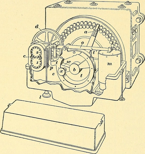
Fig. 14. now manufactured, so that it will not be required to describeit in detail. The one particular now made is shown in Fig. 14. Thisregulator is shown at C, Fig. 13, but Fig. 14 is a larger 22 ELECTRIC LIGHTING. 19 view, displaying the regulator with its rheostat detached fromthe machine. It requires no wall controller and is oper-ated by an encased magnet m connected in series with thelamps. The magnet m does not move the rheostat arm <?,but basically controls a valve that admits oil below pressureto either side of a vane or piston that swings about in theclosed chamber b. The oil pressure needed to operatethe piston is maintained by implies of a tiny rotary pump c
Text Appearing Following Image:
fig. 15. driven by a belt from the dynamo shaft running on pulley d.The decrease case is filled with oil to a point a little below therheostat-arm shaft. Fig. 15 shows the functioning components of the regulator with theouter casing removed. The pump consists of two gears1, 2, Fig. 15, meshing with each and every other. Oil is drawn fromthe decrease component of the box and discharged through the valve,which moves up and down in a chamber at e. The seriesmagnet m pulls on the lever <?, which operates against § 19 ELECTRIC LIGHTING. 23 the adjusting spring/. The valve is operated by signifies ofthe link r. The piston or vane b is movable and is free toswing about in the chamber t. The partition w is fixed, sothat when oil is pumped in above w and is allowed to flowout below, the vane b moves clockwise and moves the rheo-stat arm in the same direction. When oil is pumped in onthe reduce side and permitted to flow out on the upper, thevane moves counter clockwise. When the present is at itsnormal worth, the valve is in
Note About Photos
Please note that these images are extracted from scanned page pictures that might have been digitally enhanced for readability – coloration and appearance of these illustrations might not perfectly resemble the original perform.