Some cool wire electrical discharge machining images:
Image from web page 873 of “The street railway overview” (1891)

Image by Web Archive Book Pictures
Identifier: streetrailwayrev08amer
Title: The street railway evaluation
Year: 1891 (1890s)
Authors: American Street Railway Association Street Railway Accountants’ Association of America American Railway, Mechanical, and Electrical Association
Subjects: Street-railroads
Publisher: Chicago : Street Railway Evaluation Pub. Co
Contributing Library: Carnegie Library of Pittsburgh
Digitizing Sponsor: Lyrasis Members and Sloan Foundation
View Book Page: Book Viewer
About This Book: Catalog Entry
View All Pictures: All Images From Book
Click right here to view book on-line to see this illustration in context in a browseable on the web version of this book.
Text Appearing Just before Image:
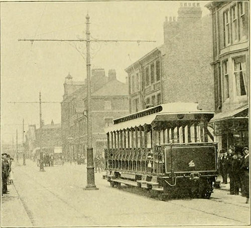
Sort OF CABS. • yise be the case. The two batteries will furnish present for100 car-miles, or six round trips. The arrangement of the switchboard enables the cells to beconnected in parallel with the overhead wire, or the feedersalone could be straight connected with the line, or the batterydisconnected with the line and coupled direct to the feeder.
Text Appearing Right after Image:
POLES AND OVERHEAD CONSTRtJCl ION. hich would be the case when the cells were getting charged.The storage battery switchboard is fitted with a recording volt-meter, measuring the drop iu the rails, ammeter and a watt-meter which registers the charge and discharge of the battery. At the rieetwood storage batteiy station there is provisionfor housing 10 vehicles. In the vehicle barn at the energy station thereis room for 12 cars, and pits for four cars to be inspected atonce. There are a quantity of machine tools for repairs in oneend of the barn. All the buildings are lighted with incandescentlamps, getting existing from a switchboard panel in the centralstation. The rolling stock comprises 16 open motor care, eight closedmotor automobiles and 3 trailers. Each motor automobile is 34 ft. 6 in.long and mounted on two bogie trucks with 2S-in. wheels. Eachcar carries 48 passengers and weighs, loaded, 12 tons. Eachtruck has a 35-h. p. motor, providing sutlicient energy to operatethe automobiles at 25 miles per hour. The
Note About Images
Please note that these images are extracted from scanned page images that could have been digitally enhanced for readability – coloration and appearance of these illustrations could not completely resemble the original function.
Image from page 92 of “The street railway overview” (1891)

Image by Net Archive Book Pictures
Identifier: streetrailwayrev15amer
Title: The street railway evaluation
Year: 1891 (1890s)
Authors: American Street Railway Association Street Railway Accountants’ Association of America American Railway, Mechanical, and Electrical Association
Subjects: Street-railroads
Publisher: Chicago : Street Railway Review Pub. Co
Contributing Library: Carnegie Library of Pittsburgh
Digitizing Sponsor: Lyrasis Members and Sloan Foundation
View Book Page: Book Viewer
About This Book: Catalog Entry
View All Images: All Images From Book
Click right here to view book on the web to see this illustration in context in a browseable on the web version of this book.
Text Appearing Just before Image:
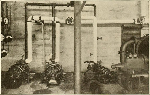
he only pieces of machinery in the buildinghaving reciprocating motion. The two major generating units consist of Westinghouse-Parsonsturbines direct connected to 400-kw. Westinghousc generators run-ning at 3.600 r. p. m. and generating current at 13,200 volts, 7,200alternations. These are believed to be the very first small turbine unitsbuilt to produce current for 13,200 volts. These turbine units aresupplied with -Mberger condensers of the dry vacuum system kind.These condensers arc erected alongside of the turbines on the mainfloor and occupy as considerably or a lot more space than the complete generatingunil. The maximum overall length of the turbines is 12 ft. four in., themaximum width 4 ft. six in. and maximum height 7 ft. six in. The totalweight of the turbine is 20,000 lb. These figures consist of only theturbine itself and not the generator direct connected to it. Exceptfor the air pumps which are connected to the condensers it is diffi-cult to see any motion of machinery in the station, even when it is
Text Appearing Right after Image:
AUXILIARY MACHINES. ill full operation as the generator armature revolves so swiftly thatthe motion is unnoticeable. The condensers are fitted with lo-in. suctions and every single con-denser has 2,000 sq. ft. of cooling surface. The circulating pumpshave four-in. suction pipes. The circulating water is handled by two 74 STREET RAILWAY Overview. [Vol. XV, No. 2 pumps operating at two,400 r. p. m. ilrivin by eight-h. p. De Laval tur-bines which run at 24.000 r. p. m. . separate view is provided herewith of the two exciter units andone of the circulating pumps, all of which arc driven by little DeLaval turbines and the small size of these units is very noticeable,occupying as they do but 3 or 4 square feet of floor space.The two c.xciters are every single of 20-kw. capacity and create at 125volts the turl)inc speed is 24,000 r. p. m. The switchboard is situated at one particular finish of the generator room suction and discharge pipes are carried in tliis identical duct with thehigh tension wiring. The higher tension lines whic
Note About Photos
Please note that these photos are extracted from scanned page photos that may have been digitally enhanced for readability – coloration and look of these illustrations may possibly not perfectly resemble the original operate.