Verify out these wire reduce electrical discharge machining pictures:
Image from web page 104 of “The street railway assessment” (1891)

Image by Net Archive Book Images
Identifier: streetrailwayrev10amer
Title: The street railway assessment
Year: 1891 (1890s)
Authors: American Street Railway Association Street Railway Accountants’ Association of America American Railway, Mechanical, and Electrical Association
Subjects: Street-railroads
Publisher: Chicago : Street Railway Evaluation Pub. Co
View Book Web page: Book Viewer
About This Book: Catalog Entry
View All Images: All Photos From Book
Click here to view book online to see this illustration in context in a browseable on the internet version of this book.
Text Appearing Ahead of Image:
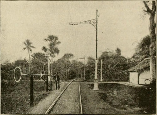
otected by a lightning arrester. The rails arc bonded with cop-per bonds of .166 sq. in. sectional location and in addition arc con-nected each and every 55 yards with wire of the very same capacity. The arrangement of the various buildings belonging to the com-pany is shown in Fig. i. In the engine area arc three generatingunits, each and every consisting o( an horizontal tandem compouiul en-gine rated at 150 h. p. at two.35 r. p. m., belted to a six-pole con-tinuous existing soo-volt generator. The generators had been suppliedby the Union I^lektricitats-Gesellschaft. of Berlin. Each enginehas two fly-wheels, 1 carrying the generator belt, and the otherthe governor belt, and the machines are arranged to run con-densing or non-condensing as preferred. A surface condenser of theWorthington kind has been installed. The pumping method is ina separate area adjoining the boiler area as shown in Fig. i.There arc two Worthington feed pumps every obtaining a capacityof 2,500 gallons per hour, two injectors obtaining a capacity of 800
Text Appearing Right after Image:
FIG. J~TK.CK SHOWI.NI, LINE COXSTRLCTION. gallons per hour, with a lift of 20 ft., and a storage tank, intowhich condenser pumps discharge fresh condensing water in addi-tion to the water returned by the surface condenser. The boilerfeed pumps draw straight from this tank, forcing the water througha Green economizer ahead of it reaches the boilers. In the boiler area are three boilers as shown in Fig. 2. Thesearc of the double drum variety, and have a heating surface of 1,030sq. ft., and a normal evaporating capacity of 3.300 lb. per hour.The drums are 6 ft. 11 in. in diameter, the upper drum getting 20ft. long and the decrease a single 23 ft. long. The two water and steamspaces arc straight connected by enclosed tubes. Each drums possibly separately fed, and any section of the feed pipes amongst theboilers and pumps may be cut off. The fuel employed is .•^ustraliancoal, despite the fact that it is proposed to make use of petroleum waste for thispurpose at an early date, as this material can be secured on thegrounds
Note About Images
Please note that these pictures are extracted from scanned page images that may possibly have been digitally enhanced for readability – coloration and look of these illustrations may possibly not completely resemble the original perform.
Image from web page 118 of “Electric toy generating for amateurs. This operate treats on the creating of electrical toys, electrical apparatus, motors, dynamos and instruments in common … By T. O’Conor Sloane ..” (1914)

Image by Web Archive Book Images
Identifier: electrictoymakin00sloa
Title: Electric toy making for amateurs. This operate treats on the generating of electrical toys, electrical apparatus, motors, dynamos and instruments in basic … By T. O’Conor Sloane ..
Year: 1914 (1910s)
Authors: Sloane, T. O’Conor (Thomas O’Conor), 1851-1940
Subjects: Electric apparatus and appliances Electric toys
Publisher: New York, The N.W. Henley publishing co.
View Book Web page: Book Viewer
About This Book: Catalog Entry
View All Pictures: All Photos From Book
Click right here to view book on the web to see this illustration in context in a browseable online version of this book.
Text Appearing Ahead of Image:
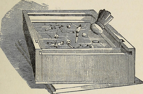
mary of the coil. No. 24 wire wouldbe a great size for each. This disposition will improve the tension of thecircuit, and will give far more powerful effects, as theapparatus is much more swiftly moved. Ano-Kato. The words ano, kato, are taken from the Greek,and mean up, down, and allude to the motions of theobjects observed in the box. The reduce shows its generalfeatures of construction. It is a shallow box whosebottom and interior sides are coated with tin-foil. Anumber of objects are created out of the lightest pith* The latter might be of the pith of cornstalks, ofelder pith, or, what is nonetheless much better, of the pith of thedry stalks of the sunflower. Tiny men with jointedlegs and arms, insects, jointed snakes, and so forth., are madeout of the pith, and might be colored with a small red ANO-KATO. 117 and black ink. The box is covered with a piece ofglass. If the glass is rubbed with a correct rubber, it be-comes electrically excited, and attracts the objects inthe box. As they rise, they touch the glass and as
Text Appearing Right after Image:
Fig. 47. Ano-Kato. they lie against it, becoming charged with the sameelectricity, are swiftly repelled. They fall into thebox and are discharged by coming against the tin-foil, which, for higher possible distinction, could be con-sidered to be in electrical communication with theearth. This operation goes on as lengthy as the rubbing iskept up. For the rubber, a pad of hair, or other material,around which a piece of kid glove is tied, is employed. 118 ELECTRIC TOT Generating. This may possibly be made much far more efficient by the use ofsome amalgam such as that utilized on electric machines. Straightforward Experiments in Static Electricity.Some simple experiments in static electricity arenext illustrated. The initial reduce shows a modification
Note About Photos
Please note that these images are extracted from scanned web page images that may have been digitally enhanced for readability – coloration and look of these illustrations might not completely resemble the original operate.